The development of a vehicle begins with identifying a need, an idea, or the realization of solving an existing problem. Today, a significant portion of this process takes place digitally. Designs are created, integrated, and validated through virtual test drives. Only after successful simulation runs does the vehicle dynamics testing commence under real-world conditions. During this phase, vehicles are tested globally under a wide range of conditions to identify and resolve even the smallest weaknesses before series production.
Particularly in the area of vehicle dynamics, a multitude of parameters must be measured with the utmost precision. For the test engineer, it is essential that measurement technology and equipment are not only reliable but also efficient to meet the increasing demands of development cycles and testing procedures.
The Application at Mercedes-Benz
At Mercedes-Benz, the development of the brand-specific driving character is a central focus. This is defined by a variety of vehicle dynamics parameters that determine how a Mercedes should feel while driving. To achieve this, these parameters are precisely measured during testing and compared to target specifications.
Accurate measurement of a vehicle’s dynamic state is of paramount importance, as the quality of the measurement signal directly influences the reliability of the parameters and, ultimately, the achievement of the Mercedes-Benz driving character.
One critical parameter in vehicle tuning is the vehicle’s slip angle. This angle represents the difference between the vehicle’s longitudinal axis and the velocity vector at a defined point of measurement. It provides valuable insights into tire and axle characteristics as well as general stability criteria. With advanced chassis systems such as rear-wheel steering, the measured slip angles can become very small. In such cases, high resolution and accuracy are essential. Only with precise slip angle measurements can nuanced adjustments be made to the vehicle, ensuring the Mercedes-Benz driving character is achieved.
Additionally, the slip angle is a location-dependent physical quantity, requiring conversions to specific reference points, such as the vehicle’s center of gravity or the rear axle, for accurate vehicle dynamics analysis. This enables objective comparisons between vehicles. For these conversions, a stable measurement signal is required to avoid numerical artifacts unrelated to driving physics.
The generation of objective parameters relies on capturing low-noise, accurate measurement signals as the basis. Slip angle measurement has traditionally been prone to significant noise due to optical measurement techniques and subsequent transformation using Fourier analysis. As a result, statistical methods and extended data recording were needed to stabilize the slip angle signal quality. This led to a trade-off between noise suppression and dynamic filtering, particularly during dynamic driving maneuvers.
New Optical Sensor Solves This Problem
The newly developed “OMS 7” sensor by Sensoric Solutions introduces an innovative approach to measuring vehicle dynamics by integrating two key technologies:
- Optical Spatial Filtering Methods: This non-contact optical technology enables precise measurement of parameters such as vehicle speed and slip angle.
- Inertial Measurement Unit (IMU): Incorporating accelerometers and gyroscopes, the IMU captures detailed data on the vehicle’s accelerations and angular rates.
By combining these technologies, the OMS 7 sensor provides comprehensive and accurate data on various vehicle dynamics parameters, including vehicle speeds, slip, pitch, and roll angles, as well as accelerations and angular rates.
Optical Spatial Filtering Method: Advantages and Disadvantages
The optical method of the OMS 7 uses an infrared LED illumination that projects onto the road surface. The reflection from the textured surface of the road is captured through a lens system onto a grid-shaped photodiode array. A deflecting mirror redirects the incoming light, enabling a compact design.
When the sensor moves above the road surface, individual texture points of the ground pass over the individual diode surfaces. Each time a texture point crosses a diode surface, an electrical voltage is generated.
The resulting signal resembles an amplitude-modulated sinusoidal wave. The amplitude of the signal depends on the reflection from the surface and is subject to significant fluctuations, rendering it unsuitable for directly determining parameters. However, the frequency of the signal is proportional to the speed of the vehicle.
To measure lateral speed, the photodiode array incorporates additional diodes. These diode surfaces are positioned at a 90° angle to each other and at a 45° angle to the direction of travel.
During straight-line motion, the frequencies from both halves of the photodiode array are equal. When the vehicle moves in a curved path, the texture points pass over the diode surfaces at an angle. This causes one frequency to decrease while the other increases. Using the ratio of these two frequencies, the velocity vector can be determined using trigonometric formulas. A subsequent calculation allows for determining the longitudinal and lateral speeds.
Advantages of Optical Technology
- Contactless, Slip-Free Measurement Principle:
Ensures precise measurements without reliance on wheel-slip-sensitive methods. - Operation on Nearly All Surfaces:
Functions effectively on various road textures, including challenging conditions. - Reliable and Proven Technology:
Widely accepted and validated in dynamic measurement applications.
Disadvantages of Optical Technology
- Limited Resolution for Path Measurement:
The system’s ability to measure exact displacement or detailed path tracking is constrained due to the limitations of optical resolution.
The Inertial Measurement Unit (IMU): Advantages and Disadvantages
IMU stands for Inertial Measurement Unit, a complete inertial system consisting of a three-axis gyroscope and a three-axis accelerometer. The three-axis configuration enables vector-based determination of rotational rate and acceleration in space. The type used here is a MEMS-based IMU (Micro-Electro-Mechanical Systems). This technology integrates miniaturized mechanical and electrical components on a microchip. Depending on the chip used, the size is only a few millimeters, allowing it to fit alongside the optical components within the sensor.
Advantages of the IMU:
- High-Dynamic System:
Capable of capturing rapid changes in motion and orientation. - High Bandwidth:
Processes a wide range of motion frequencies effectively. - High Output Rates:
Provides real-time data with fast sampling speeds.
Disadvantage of the IMU:
- Signal Drift or Offset:
The data is subject to gradual inaccuracies over time, requiring correction or calibration.
The Fusion of Both Technologies
In the optical sensor OMS 7, both technologies are combined. The fusion of optical signals and IMU data offers significant advantages:
Long-term stability of optical signals:
- Enables precise measurement of motion parameters without drift or offset.
Dynamic signals from the IMU:
- The highly dynamic data from the IMU allows for accurate capture of rapid, changing motion sequences.
By combining these characteristics, a highly precise sensor system with minimal signal noise is created. Additionally, extensive post-processing of data is no longer necessary, as motion parameters are measured directly. For example, vehicle speed and slip angle are measured with a high accuracy of up to 0.1%. Integration and offset errors are eliminated.
The measurement of accelerations and rotational rates is also performed directly via the integrated IMU platform. After the installation and alignment of a single OMS 7 sensor, the test engineer has access to more than 40 signals, enabling a precise analysis of a vehicle’s motion state.
To handle highly dynamic applications, such as lane-change maneuvers, the sensor operates with a sampling rate of 1 kHz.
Advantages for Mercedes Benz
The sensor fusion implemented by Sensoric Solutions provides Mercedes-Benz with the advantages of low-noise and real-time capable measurement of the slip angle. A significant benefit lies in addressing the error component of the slip angle signal caused by vehicle body movement. This is achieved through a correction function that detects and compensates for the roll motion. This capability is particularly critical during vehicle testing, as the objective is to analyze the slip angle of the rigid-body vehicle under planar motion conditions. This ensures that measurements accurately reflect the true dynamics of the vehicle, free from interference caused by body roll or other non-planar movements.
Additional Features of the Optical Sensor OMS 7
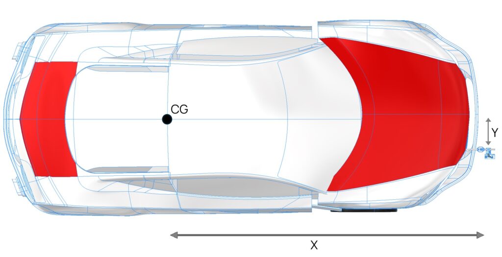
Thanks to the integrated real-time computation, the measured accelerations and rotational rates can be captured not only relative to the ground but also transformed into leveled signals. Additionally, calculated signals allow for the flexible translation of the measurement point to any desired location on the vehicle by specifying the sensor’s position relative to that point. This is easily achieved by entering the sensor’s coordinates via the integrated web interface, providing unparalleled convenience and adaptability during testing and data analysis. This capability ensures precise alignment of data to critical vehicle reference points, enhancing the accuracy and relevance of the measurements.

Figure 1: Vehicle Mounting and Geometric Measurement of the POI
This is particularly relevant because the sensor’s mounting location often does not coincide with the location of the desired measurement parameter. Since all measured values—except for rotational rates—are location-dependent, accurate conversion is critical for evaluating vehicle dynamics data. The OMS 7 provides the test engineer with over 40 signals in a flexible and user-friendly manner, available via CAN or Ethernet streams. This ensures maximum freedom in vehicle dynamics analysis.
Flexibility in Mounting
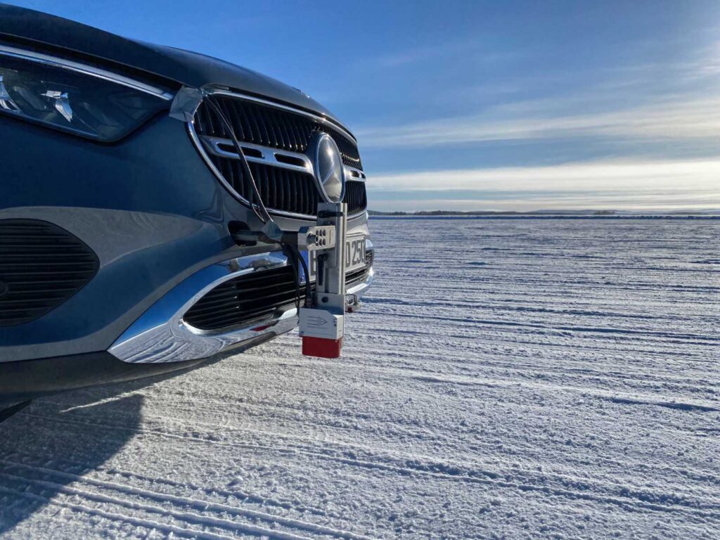
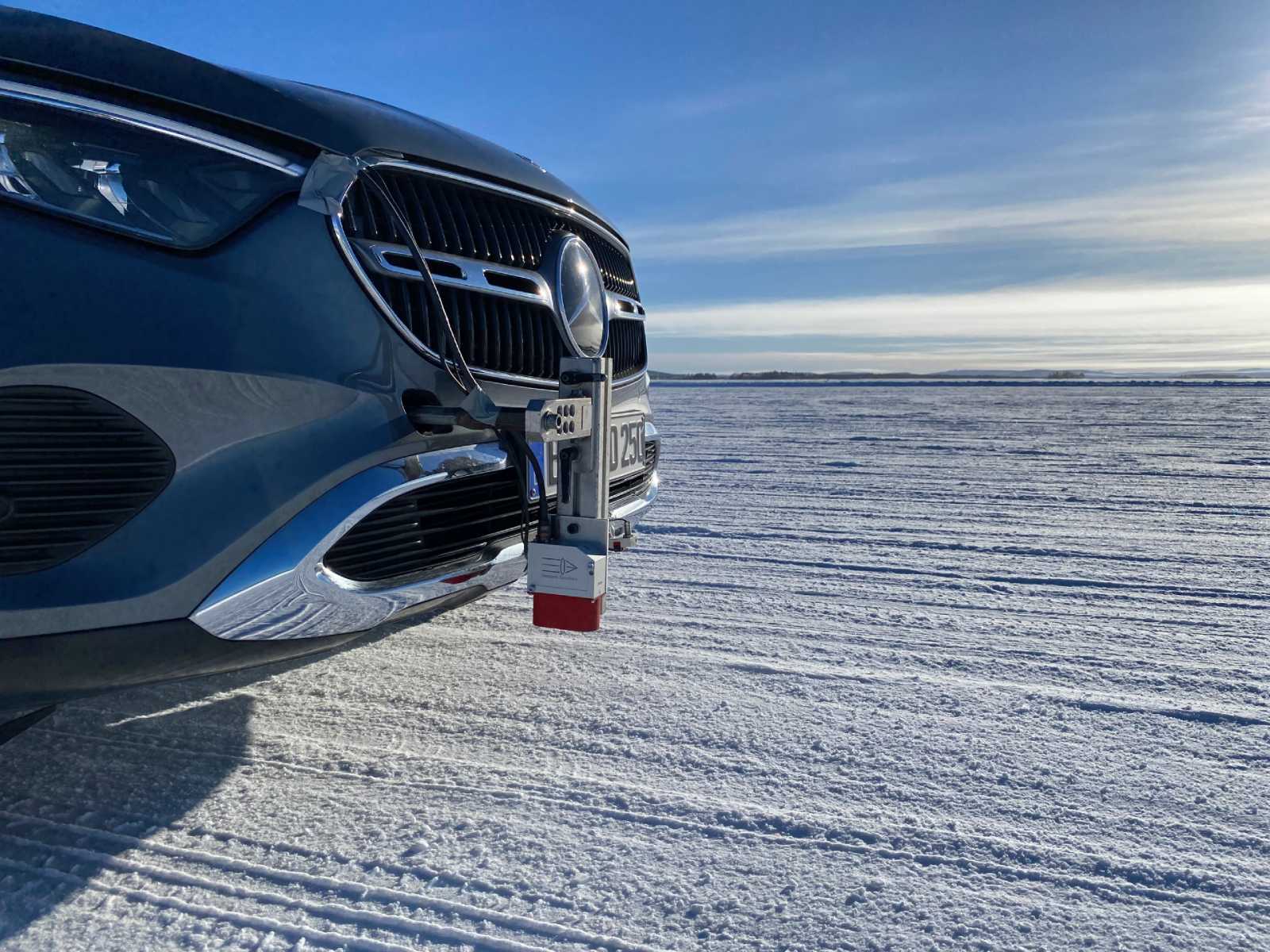
The OMS 7 can be easily mounted at virtually any location on the vehicle. A wide range of mounting options—including suction cups, magnets, and specific attachments for the tow hook or wheel—ensures flexible and straightforward installation.
With its large working range of 300 mm ± 150 mm, the OMS 7 is highly versatile and suitable for a wide variety of vehicle types, ranging from passenger cars and trucks to motorcycles.

Figure 2: The OMS 7 Sensor Mounted on the Tow Hook of a Mercedes
Intuitive Configuration
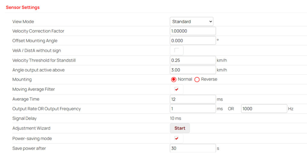
The configuration of the OMS 7 is performed via an Ethernet interface connected to the sensor’s ECU. Using a web interface, all settings and calculations can be conveniently managed without the need for additional software installation. In addition to configuring sensor parameters, the ECU handles all signal filtering, processing, and conversion. A standout feature is the ability to output both the raw optical signals and the fused measurement signals, offering unparalleled flexibility in data usage and analysis.

Figure 3: Web Interface for Sensor Configuration
Conclusion
With the OMS 7, Mercedes-Benz gains the ability to measure and evaluate objective parameters with greater accuracy and repeatability. Furthermore, new possibilities emerge for analyzing driving behavior that were previously unattainable. Even the smallest vehicle movements can now be detected and analyzed in detail.
Autors: Andreas Staiger and Philipp Röding (Mercedes-Benz), Kai Gilbert, Michael Dörr and Matthias Meurer (Sensoric Solutions)
Download Technical Article (pulished in ATTI Magazin, March 2025)
