Vehicle development begins by indentifying a need, a concept, or the realization that a current issue can be solved. Technologically, a large part of development occurs on computers, where designs are created, integrated, and evaluated in virtual test drives. Driving dynamics tests under real conditions are only conducted after successful simulation runs. Vehicles are tried out and tested under a wide variety of conditions worldwide in order to identify and resolve every conceivable weak point before the start of series production.
Development cycles are becoming shorter and shorter, while the number of validation tests to be carried out is increasing. The test engineer must be able to rely on the measurement technology. High-quality equipment, automated tests and test sequences support the test engineer and prevent incorrect measurements. This increases the quality and efficiency of testing.
In the field of vehicle dynamics, a large number of measured variables must be recorded simultaneously with maximum precision and accuracy. Complex installation of sensor technology and alignment of the equipment cost time and often reduce the effective service life of the test track.
This is where the development of Sensoric Solutions comes in:
The OMS 7 optical sensor supports test engineers in various aspects of vehcile dynamics testing. The sensor records almost all the necessary measured variables relevant to vehicle dynamics, including the vehicle speeds in the longitudinal and lateral directions, as well as the accelerations and rotation rates across all three spatial axes with outstanding accuracy. The OMS 7 records its measured variables for both longitudinal and lateral driving speeds by means of direct, non-contact measurement. Error-prone integrations are eliminated thanks to the direct optical measurement principle. For example, the travel speed and the float angle are measured directly with a high accuracy of up to 0.1 %. Integration and offset errors are eliminated.
Explanation of the optical process:
Infrared LED lighting illuminates the road surface. Reflections from the road’s textured surface are captured by a grid-shaped photodiode array through a lens system. A deflecting mirror allows the incident light to be redirected, thus enabling a compact design.
If the sensor moves above the road surface, the individual structure points of the subsurface pass through the individual diode areas. Each time a structure point passes over the diode area, an electrical voltage is generated.
The resulting signal is similar to an amplitude-modulated sinusoidal signal. The amplitude of the signal depends on the reflection of the background and is subject to strong fluctuations. It cannot be used to determine the parameters. However, the frequency of the signal is proportional to the speed traveled.
In order to be able to measure the lateral speed, the photodiode array is designed with additional diodes. The diode surfaces are positioned at a 90° angle to each other and at a 45° angle to the direction of travel.
When driving straight ahead, the frequencies of the two halves of the photodiode are the same. If the car moves on a circular path, the structure points of the ground pass through the individual diode surfaces at an angle. This results in one of the two frequencies becoming lower and the other higher. The velocity vector can now be determined from the ratio of the two frequencies using trigonometric formulas. A conversion allows the longitudinal and transverse velocity to be determined.
The features include:
- Non-contact, non-slip measuring principle
- Measuring operation possible on almost all surfaces
- Established and recognized technology
- Limited resolution of the path
What is an IMU?
The IMU (inertial measurement unit) used in the sensor is a complete inertial system consisting of a three-axis gyroscope and a three-axis accelerometer. The three-axis version allows the vectorial determination of rotation rate and acceleration in space. The type used is a MEMS-based IMU. Miniaturized mechanical and electrical components are combined on a microchip. Depending on the chip used, the size is only a few millimeters and thus fits into the sensor next to the optics.
Properties of the IMU:
- Highly dynamic system
- High bandwidth
- High output rates
- Signals are subject to a drift or offset
The fusion of both technologies
The fusion of the signals from the optics with the data from the IMU offers high added value for the user. The signals from the optics are characterized by a very high long-term stability.
The integrated IMU is subject to drift, but is characterized by highly dynamic signals.
A fusion of the long-term stable optical signal with the signals from the dynamic IMU results in a highly accurate sensor system. This also results in minimal signal noise. Direct measurement of the movement variables eliminates the need for time-consuming post-processing.
Acceleration and rotation rates are also measured directly via an integrated IMU (inertial measurement unit) platform in the sensor. After mounting and aligning a single OMS7 sensor, more than 40 signals are available to the test engineer. All these signals can be used to precisely measure the state of motion of a vehicle, thus enabling the measurement task to be solved.
With a 1 kHz sampling rate, the sensor handles highly dynamic applications effectively. This means that even dynamic lane change maneuvers can be measured in detail. The robust design of the sensor and accessories enables continuous operation even under the harshest conditions. Testing is possible from the Arctic Circle to the desert. To enable testing in road traffic, the OMS7 has LED lighting in the invisible light range. This ensures that road users are not disturbed. In addition, the integrated photoreceiver has its maximum sensitivity at infrared wavelengths.
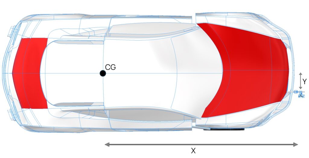
In a further step, calculated signals can be converted into horizontal signals for acceleration or rotation rates. The measuring point of all signals can also be converted to any vehicle point. This plays an important role in the application and evaluation of dynamic driving measurement data, as all measured variables, with the exception of rotation rates, are location-dependent. The OMS 7 provides the test engineer with over 40 signals for his dynamic driving measurements.
The OMS 7 can be mounted anywhere on the vehicle. However, the mounting location often does not reflect the location of the desired measured variable.
The fusion of optical signals and signals from the integrated IMU enables the conversion of measurement data for any point on the vehicle. All you have to do is enter the coordinates of the sensor on the vehicle in relation to the desired measuring point using the integrated web interface. The OMS 7 converts the signals and delivers them to the user via CAN or Ethernet stream.

Image – Vehicle attachment and geometric measurement POI etc.
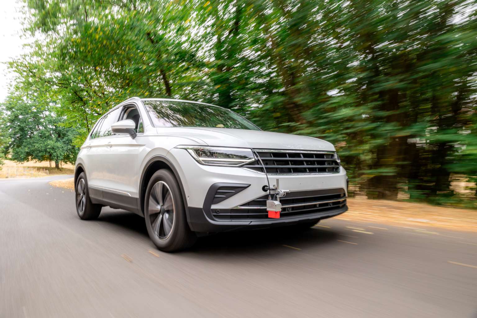
Its large working range of 350mm+/-150mm allows versatile and easy application on a wide range of vehicle types from cars and trucks to motorcycles.
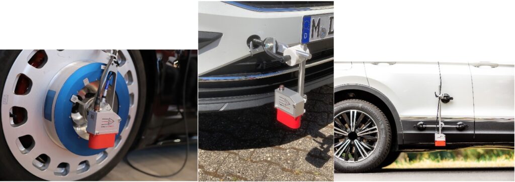
Sensoric Solutions supports the user with its extensive range of mounting accessories.

Image: Sensor mounting on the measuring wheel and chassis
Authors: Kai Gilbert, Michael Dörr
